
Building your ArdCore Board from Scratch
Please note: The Ardcore project is no longer being actively developed. SnazzyFX may still have Eurorack modules available, and others have created 'clone' boards (with my blessing). But Ardcore boards are no longer available from me or 20 Objects.
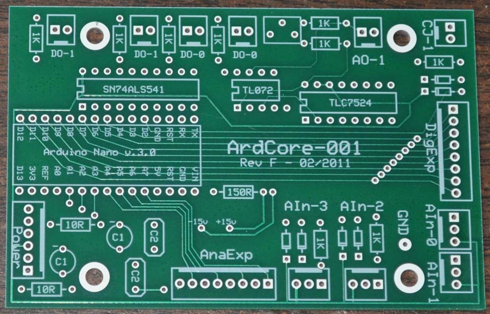
This document assumes that you purchased a bare board for the ArdCore 001 Arduino-to-Modular interface. This board was designed for our own use, and doesn’t have as much on-board documentation as many kit boards do. Hopefully, this document will help you assemble the board with a minimum of distractions!
ArdCore Board Basics
The Arduino Connection
The board is divided into a few major sections. Perhaps the most important is the Arduino Nano connection, which is laid out to support the latest version of the Nano (v3.0). However, if you want to use this with any other Arduino, you can simple place the headers (provided) into the Nano connections and use jumper cables to connect the important connections to your device.
Power Handling
The bottom-left area is used for the power connections and handling. The power connection we use is a six-pin MTA connector, but you may want to connect to some other power supply. It follows the Synthesizers.com standard (http://synthesizers.com/technical.html#internaldc), which is as follows:
All of the power connections are used, so you have to make sure you are feeding it both +/- 15VDC as well as +5VDC. Note: You probably will not want to use the Arduino's 5V output to feed this voltage, since the current draw may be enough to affect the Arduino's operations.
The capacitors used are 25V 10 uF radial capacitors for “C1” (the negative connection is marked on the board), and 100nF capacitors for “C2” (we use axial caps). The 10-ohm resistors provide some measure of protection for the circuit, and should use 1 or 2% resistors so that you don’t end up biasing the input voltages.
The 150-ohm resistor (found above the Analog Expander connection) provides a voltage reduction so that the Arduino is powered off an approximate +12V DC feed. If you are powering this from a Euro-based power supply (or your own external supply), you can replace this with a null resistor; just make sure that you aren’t powering the Arduino with more than 12VDC for its long-term health.
The +15 and -15 positions are test points that you should use to verify that you are getting a correct voltage from your power connection.
Analog Input Connections
The four on-board analog connections use a similar wiring layout to the Synthesizers.com 3-pin MTA connections (http://www.synthesizers.com/technical.html#internalpot), but with pre-defined voltages values for the outside pins:
You don't have to use MTA connectors - you can use standard wire connections. The important thing to consider about these connections are that they allow for jack, pot and switch wiring as you see fit:
For pots, wire the GND to counter-clockwise, +5V to clockwise, and Signal to the center tap.
For jacks, you must use a switched jack (because the analog inputs are 'floating', and will generate random values if unconnected). Wire the tip to the Signal input and both the sleeve and the switch to the GND input.
For switches (DPDT), wire the +5V and GND to the two switched connections, and the signal to the input.
If you want to make a jack/pot combination, use a switched jack and connect the switch to +5V.
Analog inputs 0 and 1 are meant to primarily be used for pots, so there is no incoming voltage protection. If you decide to feed these inputs with jacks, you will need to make sure that the incoming voltage stays between 0 and 5 volts. For analog inputs 2 and 3, this is provided using diodes that will "dump" excess voltage to the power rails, and a 1K resistor for impedence and voltage protection. For the diodes, we use 1N4148 diodes.
The large labeled GND pad is unused - it is provided as a ground test point for use in debugging the circuit board during build-out.
Digital Output Connection
The digital outputs (D0 and D1) are implemented using two-pin connections buffered by a LED buffer chip (the SN74ALS541).
On our production boards, we use MTA-2 connectors for these connections, but you can use a direct wire connection. This layout follows the Synthesizers.com standard (http://synthesizers.com/technical.html#internaldc) for jack connections; we combine this with a 1K current-limiting resistor to keep things clean.
The two outputs are duplicated, since the digital outputs will often have LED's that also provide visual support of the digital (typically gate) outputs.
Analog Output Connection
The analog output (labeled A0-1) provides the output of the TL072 op-amp as a 0-5VDC control voltage. This looks pretty much like the digital outputs (the pinouts of the connection are the same), but there is the extra resistor and an unlabeled box:
The extra resistor is actually part of the op-amp's feedback chain, and not directly connected to the output jack. The box is a location to place a trim pot (we use 200R as a value). In our construction, we use a single-turn trimpot, but you may want to use a multi-turn trimpot for increased stability. If you use a single-turn, it is useful to place a dab of fingernail polish to help "seal" its location.
Parts List
For ArdCore boards prior to Rev G, use the following parts list:
For Rev G and later, everything is exactly the same, but we no longer include the Trimpot (which was originally sourced locally). Instead, please use a 10-turn trimpot, 200R, Mouser part number 67WR200LF.
Have fun!